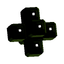
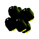
The .obj format (especially as exported by FreeCAD, which turns everything into polygons) is pretty simple, so I wrote a program to translate .obj files to the procedural shape language. The output is a lot more verbose than the input, so I'm thinking it might be nice to support the .obj format natively. In the meantime, this works.
Caveats:
- FreeCAD doesn't seem very good about listing polygon vertexes in the right order. I had to modify my fill-polygon function to draw both front and backsides of polygons or converted shapes would appear with about half their faces missing.
- My polygon renderer is not that good. With larger, simpler shapes it appeared to work well enough, but complex objects at weird angles result in images with a lot of not-so-nice-looking lines across them.
Example of the polygon artifacts (I had to rotate the shape to a very specific angle to make them this bad; most of the time they look fine):
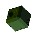
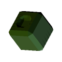
Anti-aliasing seems to help a bit but doesn't really solve the problem.
Chapter 2
Some thoughts after horsing around trying to diagnose:
- The black lines are due to shadows being casted by polygons seen nearly edge-on.
- Backsides of polygons are showing through cracks at edges. This "shouldn't happen" without rounding errors, since both polygons end up being plotted with the same x/y coordinates for the top and bottom of each edge, so should stop at the same pixel.
- Rounding errors might be accumulating due to the way we have to indicate polygons in this language. Change the transform (which may already be some wacky thing), add a point, change the transform again, add another. Another good reason to support .obj natively, which should in theory eliminate this (there may still be rounding errors, but they would be identical for every polygon in an object).
- Even with all that, the shadows casted by these funny edge artifacts seem excessive. Sometimes the edge is completely hidden, but the weird shadows appear anyway. A good next step (aside from overhauling the polygon drawing system) might be to have a post-render pass that points out extreme depth differences.
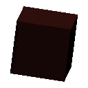
Note that for this last example, both the light lines and the weird shadows go away completely (at least I was unable to rotate the cube into a position where I saw anything) when backsides are not drawn (which I could do in this case because this cube was not imported from a FreeCAD .obj).
Chapter 3
Another attempt at cleaning up the edges.
since the problem is that at extreme angles, pixels get plotted at extreme depths (and then cast shadows on others), why not just clamp the plotted depth within the possible depths given the polygon being plotted?
Keep in mind that the way I track depth is to track the depth of each corner of each pixel. It may have been better/simpler to just track the depth of the center and the x/y slope, but for now corner depths is how it works. When plotting a polygon, a pixel is included if its center (x, y) is within the polygon. So it could well be that one of the pixel's corners is outside the polygon, and logically should have an out-of-range depth value. And if all our calculations were mathematically perfect and we didn't have to deal with the realities of floating-point rounding errors that might work. But we do, so maybe a sanity check like this would help.
Turns out it does! But as a side-effect neighboring polygons making up a face had visible creases between them where their surface normals were off due to clamping. Solution is to only do the clamping when plotting polygons with high dz/dx or dz/dy.
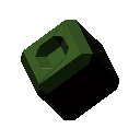

Still have the problem of backfaces showing in some places where they shouldn't, but hopefully that can be fixed by specifying polygons in a less goofy way, and anti-aliasing actually does mitigate that quite a bit.
Some random shape (I have updated entry 11 with the latest code to make this work) for your viewing pleasure:
